Posts

Week 9 Progress

Image
The most important aspect of this week was construction of the device. The tools used and progress can be seen in the image below. While building, and refining final information and calculations for our presentation, we shot footage for our introduction video. Slides were added to our presentation, and a a guide script is being developed. Last but not least, our final report exhibited minor beneficial changes, such as the addition of a budget table.

Week 8 Progress

Image
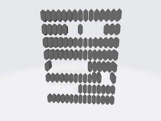
On Tuesday we applied another layer of the rubberized undercoat to the Neoprene. (We found last week's to have dried horribly (see below) due to the folding we applied to the pad when transporting it while still wet.) We also separated our first batch of scales from the raft and prepared them to be attached to the Neoprene We had made a lot of progress on our presentation; we added: Theme questions slide project objective slide references slide We interfaced with the innovation studios to get all our scales printed our and ready

Week 7 Progress

During this week we worked on and submitted our Final Report Draft. We looked up some published research papers on the topics of contact mechanics, anatomy of the knee and surface engineering. The dimensions of the neoprene foam and the D3O were determined

Week 6 Progress

Image
First and foremost, this week we found a new issue surrounding the mechanics of our proposed knee pad's contact with any flat surface. Basically when tested practically with a PLA (3D printing material), we observed that the impact on the bone is really hard and painful. To address this problem we plan to distribute shock impact. The thickness of the scales that will be used on the outside of the knee needs to be greater (larger height from the surface of the skin of an individual, protruding perpendicular outwards). To determine these exact measurements we wanted, we built a test pad, thus making it much more unlikely 3D prints would have to be run again, wasting materials. The heights which were decided were 0.5 cm for the region of the bone, 0.8 cm and 1 cm for the peripheral regions. We also submitted our 3D print design of the hexagonal scales with three different heights. The designs are displayed below.  While we wait for th...

Week 5 Progress

Image
This week we came across new research in contact mechanics that suggested we elongate our scales in order to reduce friction. At the same time, we decided to change the shape as well.  We went from octagons and squares to elongated hexagons, in order to keep the design more simple. Also, we experimented with the actual material the scales will be printed out of, and decided to half all dimensions to what is detailed below. In addition to scale progress, two adhesives were ordered. One was a plastic to rubber glue to attach the scales to the D3O sheet, and fabric to rubber glue to attach the pad on the other side of the D3O. Also, we received the D3O and found it is less shock absorbent than expected. Thus, we have purchased a sprayable rubber undercoating to thicken this layer.

Week 4 Progress

This week we had decided to tackle how to create our knee pads. We had ordered our material, a 2mm orange sheet of flexible D3O. We met with the 3D printing staff to discuss how to print our scales and what materials they would be made of, that being a hard plastic. We found information for certain adhesives. We are currently deciding on the dimensions of our scales. The shape of the entire knee pad was now decided to form an ovular shape, which would essentially be the rectangle, but the scales will be form a curved edge on the outside of the knee, essentially pulling two sides of the rectangle shape out.

Week 3 Progress

Image
In this week, we worked to brainstorm on the ideas of the design of the scales on the armor and the material to be used for the padding and shock absorption. We thought of several designs which would be suitable to use and planned out a specific model for our scale units from all sides. Top view This structure was partially inspired by the bee hive structure. An octagon is placed in the center surrounded by four squares on the sides, followed by another octagon making an intricate network of plates. The purpose is to minimize the vacant space between each unit in order to provide the maximum protection possible. The figure of the proposed design has been displayed below. Cross Sectional View This view is only limited to the scales till now. We have proposed two theories related to this- 1.  Some of the scale units should be flared out. This will help in covering the maximum area possible, not leaving behind spaces when it is straight or even bent. Hence it would e...

Week 2 Progress

We have decided on the scale-based armor as our project. We found multiple inspirations for scale shapes and patterns including; the pangolin, sharks, fish, snakes, and scale insects. We have begun preliminary sketches of the scale pattern we will use. Ideas for mounting of the protective elements on the flexible backing have been discussed. Ideas include; using a rubber backing as opposed to cloth which would possibly enable the use of an adhesive to attach the scales, and using a fabric base with lateral strips of material running through the scales which would then be stitched to the base fabric. Two group members have begun developing their skills in computer modeling to initialize scale design for 3D printing Initial Proposal has been completed and submitted for grading. We have determined that to properly make a working scale armored knee pad we would need to address several obstacles: - we would need to determine scale structure - how to attach the scale - the ty...